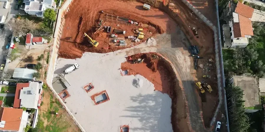
A hydraulic excavator with a long-reach arm loads out spoil from a 28-foot cut near the James River Freeway, while the engineering team logs the exposed stratigraphy. The upper five feet show stiff red clay with scattered chert fragments, transitioning into weathered limestone of the Burlington-Keokuk formation. We run this face mapping because the geotechnical design of deep excavations here depends on reading the contact between residual soil and pinnacled bedrock. Defining that interface accurately determines the bracing levels, soldier pile spacing, and whether a slope stability analysis is needed before we commit to vertical cuts. In Springfield, a missed karst pocket can change the entire support scheme overnight.
In Springfield karst, a deep excavation design lives or dies by how well you map the buried rock surface before the first bucket digs in.
Our approach and scope
Local considerations
Springfield sits on the Springfield Plateau, where Mississippian limestone is overlain by clay-rich residuum that can hold a perched water table just a few feet below the surface. We have seen excavations in the Brentwood area hit water at 8 to 12 feet during spring, turning stiff clay into a sloughing mess within hours. The bigger hazard is karst: solution-widened joints and small caves that daylight unpredictably into the cut face. A sudden loss of ground into a void destabilizes the entire support system and threatens adjacent utilities and pavement. Because Greene County lies in Seismic Design Category C with a mapped Sₛ around 0.25g, the shoring must also be checked for the seismic earth pressure increment specified in ASCE 7-22. Ignoring that combination of karst and seismicity is the fastest path to a costly excavation failure here.
Explanatory video
Relevant standards
IBC 2021 with Missouri amendments, ASCE 7-22 Minimum Design Loads (Chapter 12.13), ASTM D1586 Standard Penetration Test, ASTM D2166 Unconfined Compressive Strength of Cohesive Soil, ASTM D6032 Rock Quality Designation (RQD)
Complementary services
Shoring and Bracing Design
We produce stamped calculations and drawings for soldier pile and lagging, sheet pile, or secant pile walls. Each design includes staged excavation depths, tieback or strut levels, and a groundwater control sequence calibrated to Springfield's residual clay and limestone interface.
Karst and Rock Profile Mapping
Using a combination of SPT borings, CPT soundings, and probe drilling, we delineate the top of competent bedrock and identify solution features. This data feeds directly into the excavation support model so that bracing spans are not undermined by hidden voids.
Typical parameters
Common questions
What is the typical cost range for a deep excavation design in Springfield?
The fee typically ranges from US$2,150 to US$8,870 depending on the cut depth, linear footage of shoring, and the complexity of the karst investigation. A straightforward 15-foot basement shoring with soldier piles falls at the lower end; a 40-foot tied-back wall requiring extensive rock profiling and dewatering analysis will run higher. We provide a fixed-price proposal after reviewing the geotechnical baseline report.
How do you handle groundwater during a deep excavation in Springfield?
We analyze the perched water table typical of the Springfield Plateau residuum. If the cut intercepts the saturated zone, we design a dewatering system—usually wellpoints for shallow groundwater or deep wells with submersible pumps for cuts exceeding 25 feet. The design includes a sump and discharge plan that complies with City of Springfield stormwater requirements.
Do you need to probe for karst voids on every deep excavation site?
Almost always, yes. Mississippian limestone under most of Springfield has undergone dissolution, creating pinnacles, widened joints, and occasional small caves. We recommend probe drilling at each soldier pile location when bedrock is within the excavation zone. Skipping this step risks a sudden loss of ground that can collapse lagging and endanger workers.
Can you design an excavation next to an existing building without damaging it?
Yes. We model the lateral deflection of the shoring system and estimate the settlement trough behind the wall. For sensitive structures, we specify a stiff wall system such as secant piles and limit excavation stages to keep movements within tolerable limits. Vibration and crack monitoring on the adjacent building are always part of the construction-phase specification.